
Engine drop and bolt on mods

#31
 11-28-2011, 02:29 PM

Join Date: Nov 2008
Location: Cleveland Ohio
Posts: 677
Rep Power: 65 

I am keeping a running list of things I disassemble and remove. This is what I have so far....
Put car up on jack stands. Starting car height is 22” from bottom of engine to floor.
Car height is 32.5 inches from bottom of bumper support to the floor.
Open doors and run window down .250. Leave doors open until battery is disconnected.
Disconnect battery
Remove boost hoses from Y pipe
Remove MAF wires from left side of air filter housing
Unplug MAF
Air filter housing
Tail lights
Rear bumper
Rear inter fender wells
Exhaust
Exhaust heat shroud
Cat bypass pipes with 02 sensors intact
Turbo heat shroud
Turbo intake boost hose both sides
Intercoolers
Belly pans
Diagonal braces
Rear sway bar
Suspension angle switch and arm.
Will update as I get more done. I blew a wheel on my creeper today and ordered a new one. I also ordered a scissor type transmission jack from HF.
The garage dog is bored with this whole project

#34
11-29-2011, 03:46 AM
Join Date: Nov 2008
Location: Cleveland Ohio
Posts: 677
Rep Power: 65
The car has been a very pampered garage queen it's whole life. What a joy to work on, no rusted or stuck bolts, no dirt in the face. very clean car.
Rennfab, did you have an opportunity to gets some pics of the engine going back in?
Rennfab, did you have an opportunity to gets some pics of the engine going back in?
#35
11-29-2011, 12:00 PM
I'm putting the motor back together today from timing the cams. Installing tomorrow with any luck.
#36
11-30-2011, 12:12 PM
Been snapping photos of the install along the way of key points/areas to look at. I'll try to get it all up some time later tonight with some brief info on the basic steps to getting it back in w/o a hitch, as well as a few tips to help you avoid creating other problems down the road. It's by no means a "how-to" bible on slapping an M96.70 back into the car 
#37
11-30-2011, 01:02 PM
Join Date: Nov 2008
Location: Cleveland Ohio
Posts: 677
Rep Power: 65
Looking forward to the pics and advise Rennfab. So far this project has been a cake walk, thanks to your tips and advise.
I started making the engine cradle today. Alls I have to do is mig em together.
I have most of the "dry" stuff disassembled. Now its on to draining the coolant and the hydraulics.
I started making the engine cradle today. Alls I have to do is mig em together.
I have most of the "dry" stuff disassembled. Now its on to draining the coolant and the hydraulics.
#38
11-30-2011, 07:26 PM
Coolant is easy, just pop the pet****s on the bottom water necks and it drains down good. Then disconnect the heater core lines(the ones I showed clamped off with those pliers) and drain that down. If the *** end of the car is a bit higher than the nose, then a majority of the coolant will remain forward in the system pipes and you won't need to drain the remainder.
Once the motor is down, force the two main coolant hoses down to drain any redsidual coolant in them to keep it from dripping. I'll usually leave them clipped into the main aluminum side tubes as they rise higher than those tubes and keep fluid from dribbling out.
PS/clutch pentosin.........keep this as clean as possible. Nasty nasty fluid to get on you or rubber parts. Capping off the lines ASAP is your best bet. Reduces the amount of fluid lost/spilled. If any rubber gets wet, immediately wash with soapy water or at the bare minimum, denatured alcohol.
#39
11-30-2011, 10:06 PM
About to find out if 6SO had a post character cap  I'll break this up into a few parts so avoid posting until you see the end of it all.....
Start: Complete M96.70 all buttoned up and mated to the gearbox with slave attached. Up on a jack at the rear with my adaptor plate and on a tranny lift in the front. It's at this point that you must be 100% certain that whatever you did is right, because if not it's all coming back out again. Take it from me, not fun.

You'll want to tuck the right hand main wiring harness millspec connectors (3) so they don't snag. I do this in this fashion as pictured. Do the same for the four O2 sensor harnesses, just tuck them up and out of the way but in areas you can access later on. Tuck those in the coolant ports(dry of course) if necessary.

Slide the assembly underneath the car and position it centered in the bay left/right. Your car will likely be a bit *** high at ~32", so looking perfectly straight down the inside stamped rail you should see the motor somewhat like this. farther back than this and you'll be jockeying it around alot. It will raise up and forward when jacking. Being a lightweight(`150lbs) I find it far easier to pull the assembly from under the car via a chain vs pushing it, but that's just preference.

If you have a "dry duct" style type inlet setup, now is the time to route the piping through the suspension subframes. I'm a hardpipe type of fellow, but I make do with whatever the customers car has on at the time.

Alright, slowly start jacking the assembly up. Be mindful of the angle, trying to keep everything slightly motor-high to compensate for the angle of the car. Work rear/front in multiple alternating steps, continuously checking that you don't catch:
Oil filter housing and batter standoff
PS pump filler
Main coolant hoses
Drag the oil tank on the subframe
etc
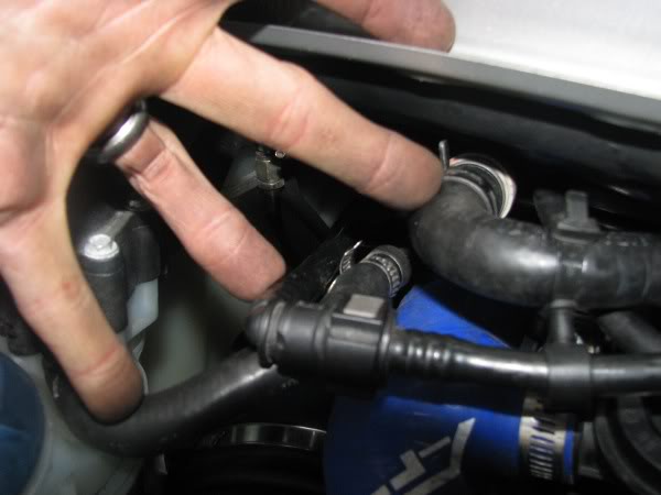
You can pull and tuck the right side main coolant hose up out of the way as pictured here

Continue to jack up the motor until you get a visual in the bay about as shown here

This is the point where you want to stop and start checking the haflshaft clearances/positioning, as well as start installing the starter motor. Feed the starter up over the right halfshaft and up itno its socket on the gearbox and lock it down with the two 15mm bolts(~30ftlbs). Attach the key trip wire to the solenoid(10mm, tighten) and the main feed cable(13mm, leave loose) as well. The cable best routes from under the starter up to the solenoid.

At about this same time/position you should be able to attach the main ground cable to the right frame rail. If not you can do it later, just don't forget.

Continue to slowly raise the drivetrain now, but at the same time paying close attention to you inlet pipes. I cannot tell you how many cars I've worked on with aftermarket inlet pipes that have been completely crushed because the tech failed to make sure the pipes did not get pinched in between the starter motor and suspension subframes. The left side there is little to worry about but on the right side the hose must fall in front of the starter.
Here:

Shown below much better how it should be routed.....You DO NOT want it up in that space there between the starter and coolant pipe.....that space is going to get real small really quick here....

Next page........
I'll break this up into a few parts so avoid posting until you see the end of it all.....Start: Complete M96.70 all buttoned up and mated to the gearbox with slave attached. Up on a jack at the rear with my adaptor plate and on a tranny lift in the front. It's at this point that you must be 100% certain that whatever you did is right, because if not it's all coming back out again. Take it from me, not fun.
You'll want to tuck the right hand main wiring harness millspec connectors (3) so they don't snag. I do this in this fashion as pictured. Do the same for the four O2 sensor harnesses, just tuck them up and out of the way but in areas you can access later on. Tuck those in the coolant ports(dry of course) if necessary.
Slide the assembly underneath the car and position it centered in the bay left/right. Your car will likely be a bit *** high at ~32", so looking perfectly straight down the inside stamped rail you should see the motor somewhat like this. farther back than this and you'll be jockeying it around alot. It will raise up and forward when jacking. Being a lightweight(`150lbs) I find it far easier to pull the assembly from under the car via a chain vs pushing it, but that's just preference.
If you have a "dry duct" style type inlet setup, now is the time to route the piping through the suspension subframes. I'm a hardpipe type of fellow, but I make do with whatever the customers car has on at the time.
Alright, slowly start jacking the assembly up. Be mindful of the angle, trying to keep everything slightly motor-high to compensate for the angle of the car. Work rear/front in multiple alternating steps, continuously checking that you don't catch:
Oil filter housing and batter standoff
PS pump filler
Main coolant hoses
Drag the oil tank on the subframe
etc
You can pull and tuck the right side main coolant hose up out of the way as pictured here
Continue to jack up the motor until you get a visual in the bay about as shown here
This is the point where you want to stop and start checking the haflshaft clearances/positioning, as well as start installing the starter motor. Feed the starter up over the right halfshaft and up itno its socket on the gearbox and lock it down with the two 15mm bolts(~30ftlbs). Attach the key trip wire to the solenoid(10mm, tighten) and the main feed cable(13mm, leave loose) as well. The cable best routes from under the starter up to the solenoid.
At about this same time/position you should be able to attach the main ground cable to the right frame rail. If not you can do it later, just don't forget.
Continue to slowly raise the drivetrain now, but at the same time paying close attention to you inlet pipes. I cannot tell you how many cars I've worked on with aftermarket inlet pipes that have been completely crushed because the tech failed to make sure the pipes did not get pinched in between the starter motor and suspension subframes. The left side there is little to worry about but on the right side the hose must fall in front of the starter.
Here:
Shown below much better how it should be routed.....You DO NOT want it up in that space there between the starter and coolant pipe.....that space is going to get real small really quick here....
Next page........
#40
11-30-2011, 10:43 PM
Moving on.
Go up in the engine bay at this point, and if you already have not removed the two rear engine mounts do so at this time. You need only to remove the two 13mm bolts holding the mount to the riser. Leave the risers and their single 13mm bolt attached to the chassis. While not a necessary step, this aliviates having to have eyes both above and below the car to align studs, as well as making some room up top in those areas.

By this time the motor should be ~75% of the way up into the bay. At this point you want to start watching the transmission mount and it's appropriate alignment with the two drop studs coming off the steel support on the chassis. This is going to be a tight squeeze between the studs and coolant hoses in that vicinity, so you want to make sure you don't jamb the metal up in there too quickly and damage the pipes. Jack the front up while watching the alignment, making adjustments as necessary to align the mount over the two studs. You'll have to force the two rubber hoses around but do not need to remove them. Once over the studs, jack it up until you can get enough thread protrusion to thread the two 15mm nuts on. If you have to jack it up quite a ways, just be certain the motor stays somewhat level throughout the process. Once the nuts are on, jack the tranny up until it bottoms on the mount, then spin the nuts up completely by finger but DO NOT tighten at this time.

Take the front propshaft now, lift and shove forward, and then pull it up into alignment with the yoke pilot on the gearbox. Thread the three 15mm bolts in and torque to 60ftlbs. I use blue threadlocker on these as well. I counter the shaft with a long screwdriver at the flange. Picture shows it up there prior to seating the tranny mount over the studs. Can be done before or after, doesn't matter.

Now fit the forward tranny steel support plate. Start by threading the forward two side bolts in by hand, THEN lift the plate up into the floor panel and affix the four 15mm nuts. Again, thread all these down but leave loose. The plate must float at this time.

Move back out into the engine bay area. Slowly jack up the motor now so there's about 6-8" between the bay roof and the top of the plenum. Now we can start plugging some bits in. Start with the main millspec connectors on the right side. They only go one way, and are color coded. do your best to ensure they fully lock, they rotate about 30-45 degrees or so to full lock. There is also the one rectangular connector which you can see dangling in the shadow to the left of the lower millspec. Don't forget that one, it eventually clips onto a tab between the two millspecs. Upper rect connector is for the decklid

With those connected move onto the main coolant tube on the right side. I always put a bit of synthetic grease on these orings. They tend to stick like a **** when you go to remove them for service work and the grease helps prevent this, but the grease also does a good deal to help them slide into place. Jack the motor up until you can get this to lock in

Go head and feed your O2 sensor wires up through their appropriate clips on the aluminum cradle, and lock them into their respectful connectors on the chassis

Loosely drop the two rear engine mounts back into the respectful risers. they only go one way, can't screw them up. Thread the 13mm bolts down so a little play remains in the mounts. Motor should now be high enough to connect the fuel lines on the left side. This is all dependent on your cars fuel system setup, but I always remove the two connection at the rails below the inlet. One 10mm pinch clamp and one 19mm coupler. Some people will disconnect the main line at the fuel filter, but this is a PITA in my opinion.

Now feed the 1" water pump bypass hose up to the lower port on the coolant reservoir and affix that. #$%^@#$%@# spring clamps are the bane of my existence . you can also snap the left side main coolant hose into the thermostat housing now

Move directly above these and connect the tank EVAP/purge lines. small one snaps into the hard clip, while the large one pushes straight into the white coupler. Don't forget to secure the gray C-clip in between the black push collar and the white body of this line. You can also connect the coolant purge line to the upper reservoir port near the vent cap.
next page....
Go up in the engine bay at this point, and if you already have not removed the two rear engine mounts do so at this time. You need only to remove the two 13mm bolts holding the mount to the riser. Leave the risers and their single 13mm bolt attached to the chassis. While not a necessary step, this aliviates having to have eyes both above and below the car to align studs, as well as making some room up top in those areas.
By this time the motor should be ~75% of the way up into the bay. At this point you want to start watching the transmission mount and it's appropriate alignment with the two drop studs coming off the steel support on the chassis. This is going to be a tight squeeze between the studs and coolant hoses in that vicinity, so you want to make sure you don't jamb the metal up in there too quickly and damage the pipes. Jack the front up while watching the alignment, making adjustments as necessary to align the mount over the two studs. You'll have to force the two rubber hoses around but do not need to remove them. Once over the studs, jack it up until you can get enough thread protrusion to thread the two 15mm nuts on. If you have to jack it up quite a ways, just be certain the motor stays somewhat level throughout the process. Once the nuts are on, jack the tranny up until it bottoms on the mount, then spin the nuts up completely by finger but DO NOT tighten at this time.
Take the front propshaft now, lift and shove forward, and then pull it up into alignment with the yoke pilot on the gearbox. Thread the three 15mm bolts in and torque to 60ftlbs. I use blue threadlocker on these as well. I counter the shaft with a long screwdriver at the flange. Picture shows it up there prior to seating the tranny mount over the studs. Can be done before or after, doesn't matter.
Now fit the forward tranny steel support plate. Start by threading the forward two side bolts in by hand, THEN lift the plate up into the floor panel and affix the four 15mm nuts. Again, thread all these down but leave loose. The plate must float at this time.
Move back out into the engine bay area. Slowly jack up the motor now so there's about 6-8" between the bay roof and the top of the plenum. Now we can start plugging some bits in. Start with the main millspec connectors on the right side. They only go one way, and are color coded. do your best to ensure they fully lock, they rotate about 30-45 degrees or so to full lock. There is also the one rectangular connector which you can see dangling in the shadow to the left of the lower millspec. Don't forget that one, it eventually clips onto a tab between the two millspecs. Upper rect connector is for the decklid
With those connected move onto the main coolant tube on the right side. I always put a bit of synthetic grease on these orings. They tend to stick like a **** when you go to remove them for service work and the grease helps prevent this, but the grease also does a good deal to help them slide into place. Jack the motor up until you can get this to lock in
Go head and feed your O2 sensor wires up through their appropriate clips on the aluminum cradle, and lock them into their respectful connectors on the chassis
Loosely drop the two rear engine mounts back into the respectful risers. they only go one way, can't screw them up. Thread the 13mm bolts down so a little play remains in the mounts. Motor should now be high enough to connect the fuel lines on the left side. This is all dependent on your cars fuel system setup, but I always remove the two connection at the rails below the inlet. One 10mm pinch clamp and one 19mm coupler. Some people will disconnect the main line at the fuel filter, but this is a PITA in my opinion.
Now feed the 1" water pump bypass hose up to the lower port on the coolant reservoir and affix that. #$%^@#$%@# spring clamps are the bane of my existence
. you can also snap the left side main coolant hose into the thermostat housing nowMove directly above these and connect the tank EVAP/purge lines. small one snaps into the hard clip, while the large one pushes straight into the white coupler. Don't forget to secure the gray C-clip in between the black push collar and the white body of this line. You can also connect the coolant purge line to the upper reservoir port near the vent cap.
next page....
#42
11-30-2011, 11:08 PM
Onwards and upwards, literally.
Now jack the motor up until the motor mounts start to lift. You'll want to wiggle them around and engage the square spigot at their base into the square openings in the aluminum cradle. Quite easy. Once there, spin the 19mm base nuts onto the mount studs and torque them down. Lower the engine slightly and ensure that the mounts are sitting flush to their risers. torque their 13mm bolts down ~25ftlbs.
Now take the tension off the engine side jack and go back underneath to the transmission mount. Tighten and torque up these bolts/nuts now to 48ftlbs.
Boom, motor is in. now some other misc BS.......
While under the car in that area let's hook up the shifter cables. easy to do, but easy to screw up and cost you a tow home. both cables have a pair of lock tabs that MUST FULLY engage their notches in the cable support. If they do not the cables will pop off the support and you will lose function of that shift gate. Ensure that the tab are seated in their notches. They're a little different between the two cables. If they don't snap in, pull the cable out and spread the tabs a little and repeat. The cable ends can then just be hand-snapped over the ball suds on the shift levers.

Two more electrical connection while under there.........plug in the reverse light switch at the front-right corner of the gearbox. Now is also the time to feed over and attch the main batter cable to the back of the solenoid(at the 13mm nut that I told you to leave loose) yes, tighten that nut now
Up top in the bay it's time to hook up the hydro pump and AC lines. Pump lines first. start by placing down a rag or two and an absorbent cloth over the main coolant hose and serp belt. I've said it a dozen times, Pentosin is bad for rubber not meant to work in it. Take whatever precautions to avoid spilling.

I'll always dump the PS lines into a can after uncapping to let fluid run out. Reduces spillage in the process. Take the return line first and push that straight into the reservoir QD port until it bottoms. The pressure feed line is a messy one, and if you've capped the port like I mentioned prior, prepare for some fluid to run out. Work quickly but diligently. The brass QD connector can be threaded by hand, uses two 15mm wrenches to tighten. Don't overtighten as it seals via an oring and you just risk breaking the fitting($$$$$$ to replace the pump). Tighten enough that it will not loosen.
After their connected, you can route and attach the AC lines. Simple enough, but I recommend new viton orings as the old ones will have certainly taken a set(usually tapered).
Underneth you're basically down to hooking up the heater core hoses/tubes, clutch feed line(just like the other brass QD fitting), and misc supports adn crossbeams. Swaybar, etc. All pretty self explanatory there.
When attaching and torquing the halfshaft allen bolts I mentioned my trick with the rotors. Here's a couple pictures showing driver placement, as well as the appropriate vane to lock against.

It doesn't matter which side you torque against, as long as you're placing the driver to wedge against the solid vanes, not the split vanes. Using this trick I can have all the bolts torqued up in under 60 seconds. Does not damage to any part, and if you're worried about chipping paint on the caliper, then just slip a piece of hose over the drive and shown in the pic above.
Certainly beats having to crawl out from under the car a half-dozen times to lock/unlock the ebrake.

That's basically the jist of it. If you run into something you're not sure about pop it up here and myself or someone else will surely see and answer
Now jack the motor up until the motor mounts start to lift. You'll want to wiggle them around and engage the square spigot at their base into the square openings in the aluminum cradle. Quite easy. Once there, spin the 19mm base nuts onto the mount studs and torque them down. Lower the engine slightly and ensure that the mounts are sitting flush to their risers. torque their 13mm bolts down ~25ftlbs.
Now take the tension off the engine side jack and go back underneath to the transmission mount. Tighten and torque up these bolts/nuts now to 48ftlbs.
Boom, motor is in. now some other misc BS.......
While under the car in that area let's hook up the shifter cables. easy to do, but easy to screw up and cost you a tow home. both cables have a pair of lock tabs that MUST FULLY engage their notches in the cable support. If they do not the cables will pop off the support and you will lose function of that shift gate. Ensure that the tab are seated in their notches. They're a little different between the two cables. If they don't snap in, pull the cable out and spread the tabs a little and repeat. The cable ends can then just be hand-snapped over the ball suds on the shift levers.
Two more electrical connection while under there.........plug in the reverse light switch at the front-right corner of the gearbox. Now is also the time to feed over and attch the main batter cable to the back of the solenoid(at the 13mm nut that I told you to leave loose) yes, tighten that nut now
Up top in the bay it's time to hook up the hydro pump and AC lines. Pump lines first. start by placing down a rag or two and an absorbent cloth over the main coolant hose and serp belt. I've said it a dozen times, Pentosin is bad for rubber not meant to work in it. Take whatever precautions to avoid spilling.
I'll always dump the PS lines into a can after uncapping to let fluid run out. Reduces spillage in the process. Take the return line first and push that straight into the reservoir QD port until it bottoms. The pressure feed line is a messy one, and if you've capped the port like I mentioned prior, prepare for some fluid to run out. Work quickly but diligently. The brass QD connector can be threaded by hand, uses two 15mm wrenches to tighten. Don't overtighten as it seals via an oring and you just risk breaking the fitting($$$$$$ to replace the pump). Tighten enough that it will not loosen.
After their connected, you can route and attach the AC lines. Simple enough, but I recommend new viton orings as the old ones will have certainly taken a set(usually tapered).
Underneth you're basically down to hooking up the heater core hoses/tubes, clutch feed line(just like the other brass QD fitting), and misc supports adn crossbeams. Swaybar, etc. All pretty self explanatory there.
When attaching and torquing the halfshaft allen bolts I mentioned my trick with the rotors. Here's a couple pictures showing driver placement, as well as the appropriate vane to lock against.
It doesn't matter which side you torque against, as long as you're placing the driver to wedge against the solid vanes, not the split vanes. Using this trick I can have all the bolts torqued up in under 60 seconds. Does not damage to any part, and if you're worried about chipping paint on the caliper, then just slip a piece of hose over the drive and shown in the pic above.
Certainly beats having to crawl out from under the car a half-dozen times to lock/unlock the ebrake.
That's basically the jist of it. If you run into something you're not sure about pop it up here and myself or someone else will surely see and answer
#43
12-01-2011, 08:06 AM
Join Date: Nov 2008
Location: Cleveland Ohio
Posts: 677
Rep Power: 65
WOW!! What a great write up Rennfab. Thank you soo much for taking the time and effort to put this together. I'm sure your incite will help tons of fellow members.
#44
12-02-2011, 01:22 PM
Join Date: Nov 2008
Location: Cleveland Ohio
Posts: 677
Rep Power: 65
The project is moving along very smoothly. Got all the coolant drained and lines removed. I really took my time with this. I would just crack the line and let it drain before yanking it off. This really kept the mess to a minimum. I also plugged each line and opening. I was worried about the main coolant lines being stuck. I took Rennfabs advice and soaked these with wd40 a week ago. A couple of tugs and they popped right out.
Next I am going to lower the engine about four inches to give me some room. Then going to take a motive bleeder and pump as much penstosin out as possible. Then remove the whole slave assembly. That will do it for the underside.
On the top side I was considering removing the A/C compressor and keep the lines intact.