When you click on links to various merchants on this site and make a purchase, this can result in this site earning a commission. Affiliate programs and affiliations include, but are not limited to, the eBay Partner Network.
Also, thanks for noting the contributions of various people to the greater community. The ability to reach out to all these good people for advice or comments is great - especially when one considers how relatively few of these cars are around.
Wow, it gets better and better, a very well written document if I might say so.
I have a million questions but will try to keep it to below 100 to preserve your sanity
The parts list is very comprehensive and I didn't realise how well thought out solution you created and in particular, the work you've done to avoid any destructive changes to the existing car's electronics, absolutely perfect.
I read through everything and just wanted to check a few points, things that I was not too sure about.
- Page 2: At that top, where you are referring to the part numbers, you mention that P-01 is part number 1, whilst P-24 is part number 14, shouldn't that be P-24 is part number 24? Just want to be absolutely sure.
- For Part Number 2 - the LCD screen, I'm trying to find a suitable one on Amazon.co.uk as I am in the UK, or ebay.
- For Part number 16, you have referenced 4 different parts on the digikey website. One of these is the connector, part GT17-2428SCF, and it looks like a female connector that sits inside one of the HIROSE plugs that form the connection between the screen and the existing car loom. How many do I need to get, do I get 10, 20? Secondly, don't I need a set of female connectors and a set of male connectors, different ones for the screen side and different ones for the loom side?
- Page 15-16: I have read through the wiring for connecting the pass through wires between the loom connector (LC) and the screen connector (SC) and also the redirection of the red,green, blue and CSYNC wires to the hardware connector (HC). It makes sense, but, when you say connect pins 1, 2, 6 and 8 from the SC to the HC, I am confused. Just so that I get it straight, I am plugging the SC into the screen's socket, the LC into the car's loom plug and the HC into the new hardware, this mean that I am taking the pins 1,2,6 & 8 from the screen to the new hardware, but shouldn't I be taking them from the LC to the HC, ie. from the circuit that is coming from the car not the screen?
- Page 19: I think it's more applause than the world's smallest violin, given the complexities you have crossed to get this all to work !!! This is a seriously well put together process.
- applying the screen protector before you fit the screen is a great tip.
- Page 20: Do you have the plan for the acrylic box, perhaps in DXF or other vector based file format?
- Page 21 - You mentioned that we need to modify the RGB to HDMI boxes, so do I need to buy two of these? I am guessing that these two are for the front and rear cameras, so if I don't want to use the cameras, I don't need these do I?
- Page 28: The sync inverter. I bow to your skill here, using an oscilloscope to get the inverter working - OMG
- Page 29: For the SN74HC04N inverter. I can see on the breadboard that you have tied 2A/3A/4A/5A/6A together and it looks like they are then tied to the Vcc/5v line, is that right?
- Page 31: EEEEKKKKK - that is one scarey power loom, and yes, looks like an octopus .... But I get it, good idea to bring everything together off of one power source, clean and logical.
I am excited to learn about the Raspberry Pi and how you have set it up as a CarPlay interface, can't wait
One more question, is there any chance of a wiring diagram when you get to the end, I know that is a lot to ask, but it would help us simple folk get an even better understanding. I could try to create a simple one from reading through everything and then send it over if that would help?
Wow, it gets better and better, a very well written document if I might say so.
I have a million questions but will try to keep it to below 100 to preserve your sanity
The parts list is very comprehensive and I didn't realise how well thought out solution you created and in particular, the work you've done to avoid any destructive changes to the existing car's electronics, absolutely perfect.
I read through everything and just wanted to check a few points, things that I was not too sure about.
Thanks very much. From the length of it you can see why I resisted starting it...it's quite the opus.
I've extracted your questions to answer them in order...
- Page 2: At that top, where you are referring to the part numbers, you mention that P-01 is part number 1, whilst P-24 is part number 14, shouldn't that be P-24 is part number 24? Just want to be absolutely sure.
> Yes, you're correct. I'm a doofus. I have changed for the next version.
- For Part Number 2 - the LCD screen, I'm trying to find a suitable one on Amazon.co.uk as I am in the UK, or ebay.
> I didn't get mine from Amazon 'cos I couldn't find one. Hence why I spun the random satisfaction wheel of ebay.
- For Part number 16, you have referenced 4 different parts on the digikey website. One of these is the connector, part GT17-2428SCF, and it looks like a female connector that sits inside one of the HIROSE plugs that form the connection between the screen and the existing car loom. How many do I need to get, do I get 10, 20? Secondly, don't I need a set of female connectors and a set of male connectors, different ones for the screen side and different ones for the loom side?
> The P-13 I referenced comes with all the pins installed. The other side requires a jigsaw like construction. I'm glad you asked about pins since I referenced the wrong insulator as it should be the 10 pin version. Hence, there are 10 pins required to construct it. This means I need to update parts P-14 and P-15 - apologies! You can likely find the parts by searching but I'll upload the new version shortly.
- Page 15-16: I have read through the wiring for connecting the pass through wires between the loom connector (LC) and the screen connector (SC) and also the redirection of the red,green, blue and CSYNC wires to the hardware connector (HC). It makes sense, but, when you say connect pins 1, 2, 6 and 8 from the SC to the HC, I am confused. Just so that I get it straight, I am plugging the SC into the screen's socket, the LC into the car's loom plug and the HC into the new hardware, this mean that I am taking the pins 1,2,6 & 8 from the screen to the new hardware, but shouldn't I be taking them from the LC to the HC, ie. from the circuit that is coming from the car not the screen?
> Correct again (damn, you were paying attention). I knew what I was talking about but failed to document what I meant. I'll amend in the next version. The R/G/B/S come from the car loom and go into the new hardware box. The other pins are passthrough. The ground is special since it needs to both pass through and link to the hardware box.
- Page 19: I think it's more applause than the world's smallest violin, given the complexities you have crossed to get this all to work !!! This is a seriously well put together process.
> Cheers, again.
- applying the screen protector before you fit the screen is a great tip.
> Yep. Experience is a painful teacher.
- Page 20: Do you have the plan for the acrylic box, perhaps in DXF or other vector based file format?
> SVG can be opened directly by Inkscape, which since it's free I recommend you look at. I can look at another format if that would be useful for you.
- Page 21 - You mentioned that we need to modify the RGB to HDMI boxes, so do I need to buy two of these? I am guessing that these two are for the front and rear cameras, so if I don't want to use the cameras, I don't need these do I?
> Correct, and I'd hoped to make that clear. One box per camera...neither required if no cameras.
- Page 28: The sync inverter. I bow to your skill here, using an oscilloscope to get the inverter working - OMG
> You should see the pile of tiny amps and boosters I made...much more Edison than Tesla, here in my shop
- Page 29: For the SN74HC04N inverter. I can see on the breadboard that you have tied 2A/3A/4A/5A/6A together and it looks like they are then tied to the Vcc/5v line, is that right?
> Noooo - just tied the unused inputs together. The input you use is separate. The Vcc and GND are separate.
- Page 31: EEEEKKKKK - that is one scarey power loom, and yes, looks like an octopus .... But I get it, good idea to bring everything together off of one power source, clean and logical.
> Trust me, if you have a better idea I"m all ears. I put connectors in the cables so I could replace it later with something better but it's working and I haven't had any epiphanies. It's also absolutely key that all electronic components share the same ground since that's how the pull up/pull down works. If you use different grounds they can be at different voltages - it's all relative.
I am excited to learn about the Raspberry Pi and how you have set it up as a CarPlay interface, can't wait
> Next version of the document!
One more question, is there any chance of a wiring diagram when you get to the end, I know that is a lot to ask, but it would help us simple folk get an even better understanding. I could try to create a simple one from reading through everything and then send it over if that would help?
It's not a lot to ask at all - and I should have really done it already. I'll find some open source software to help me convey the cats' cradle of wires in a way that makes sense.
Okay, good people...here is v0.3 of the how-to. It's more or less complete, pending Madgadget's excellent reviewing skills.
<link removed>
Yes, it's 130 Mb in size due to all the images I've included. No, it's not packed with a virus.
Note: I'm double checking on the Hirose connectors. I sourced mine from a couple of different places that no longer stock them so I'm trying to get them all from Digi-Key (who are excellent, BTW). As such, I've ordered all the parts on the how-to in order to make sure they match the ones I used. Never say I don't do anything for you ;-)
Madgadget: what wiring diagram did you want? All the connections or just the power or just the A/V? Let me know and I'll cook something up.
An excellent document, it reads clearly and everything makes complete sense, what a journey, from your original posting, to this work of art.
The wiring diagrams dotted throughout are perfect, they are the icing on the cake.
And the SVG for the hardware casing is spot on, thank you for including that too
To be honest, I think you have cracked it, it all looks really good. I just have a few questions, mainly 'cos I'm being dumb;
- For the replacement screen, after you have extended the IR receiver to enable you to adjust the screen properties once it is installed. Where did you locate the receiver, is it best in the opening where the screen comes up or did you move it down to the footwell where the new box lives?
- Page 18: The schematic diagram is perfect, but Ummm, in the text above, shouldn't it say that the Red, Green, Blue and the CSYNC should be taken from the LC to the HC. sorry to be picky
- Page 42: For the audio hook up, am I right in thinking that because you have an HDMI switch that seperates the audio into a seperate feed, any device that has audio and is plugged into the HDMI switch, will have it's audio taken from the switch, rather than using an audio out from that device? if that makes sense?
Oh and my vantage is a lowly 2007 which didn't have any auxilary input for the audio or bluetooth, I had to fit a MOST interface for the audio inputs/bluetooth etc, so I can feed into that.
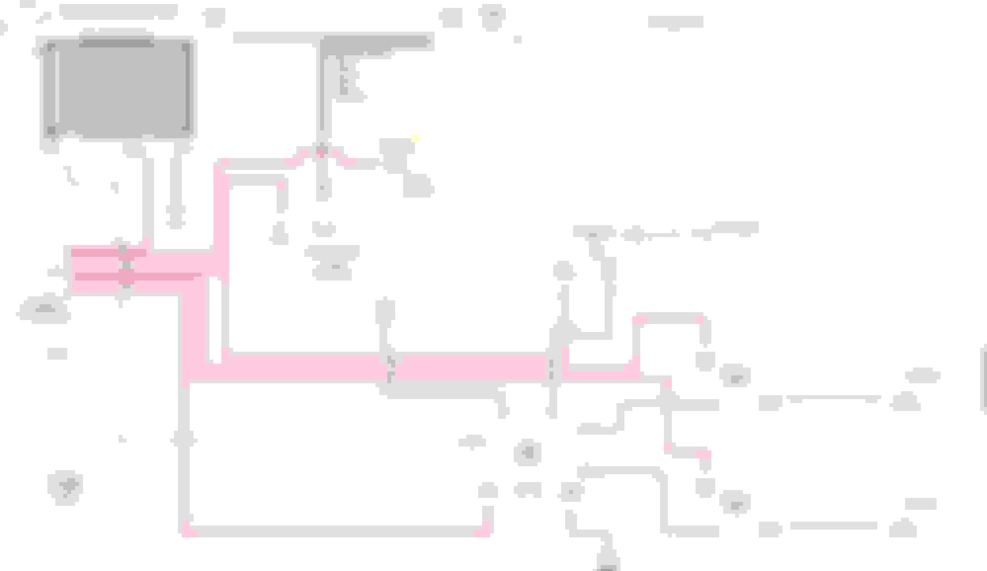
Lastly, I thought I would knock up a wiring diagram to help as you have done so much, is that any good? did it in an old version of MS Visio, is that any good to include? actually, more to the point, is it right?
An excellent document, it reads clearly and everything makes complete sense, what a journey, from your original posting, to this work of art.
The wiring diagrams dotted throughout are perfect, they are the icing on the cake.
And the SVG for the hardware casing is spot on, thank you for including that too
To be honest, I think you have cracked it, it all looks really good. I just have a few questions, mainly 'cos I'm being dumb;
- For the replacement screen, after you have extended the IR receiver to enable you to adjust the screen properties once it is installed. Where did you locate the receiver, is it best in the opening where the screen comes up or did you move it down to the footwell where the new box lives?
- Page 18: The schematic diagram is perfect, but Ummm, in the text above, shouldn't it say that the Red, Green, Blue and the CSYNC should be taken from the LC to the HC. sorry to be picky
- Page 42: For the audio hook up, am I right in thinking that because you have an HDMI switch that seperates the audio into a seperate feed, any device that has audio and is plugged into the HDMI switch, will have it's audio taken from the switch, rather than using an audio out from that device? if that makes sense?
Oh and my vantage is a lowly 2007 which didn't have any auxilary input for the audio or bluetooth, I had to fit a MOST interface for the audio inputs/bluetooth etc, so I can feed into that.
Lastly, I thought I would knock up a wiring diagram to help as you have done so much, is that any good? did it in an old version of MS Visio, is that any good to include? actually, more to the point, is it right?
Now it's my turn to applaud - nicely done on the wiring diagram. Just two edits at first glance:
You're missing the shared/common ground for the circuit
The 12V supply from the power distribution goes to the 12V/5V step down buck converter...which is where the 5V comes from
The 12V supply feeds the cameras
I'll happily merge this into the document - let me know how you want to be attributed.
The IR receiver is on the lip of the screen unit base so I can point the remote down into the now open dashboard when the screen comes up. Way easier to route here than put it in the footwell. I'll take a picture and add that to the how-to.
I tried to unconfuse the wiring for the video and epically failed again. I've changed the language in the next version that I'll upload once you tell me about the attribution.
- Page 42: For the audio hook up, am I right in thinking that because you have an HDMI switch that seperates the audio into a seperate feed, any device that has audio and is plugged into the HDMI switch, will have it's audio taken from the switch, rather than using an audio out from that device? if that makes sense?
The audio question: yes, anything that is the current HDMI source will be running through the audio. However, you can either plug directly into the pi�s 3.5 mm audio port or get one of the tiny USB sound cards. Either would give you pi audio regardless of HDMI source. I�ve verified it works.
Is it possible to install Pioneer DMH-WC6600NEX in place of factory screen ? With its modular design and wireless carplay/android auto, it seems doable. https://www.pioneerelectronics.com/P.../DMH-WC6600NEX
Any thoughts ?
Is it possible to install Pioneer DMH-WC6600NEX in place of factory screen ? With its modular design and wireless carplay/android auto, it seems doable. https://www.pioneerelectronics.com/P.../DMH-WC6600NEX
Any thoughts ?
The screen size to replace the stock is very specific and this is way too big. I wanted to find a stock android head unit to make this easier but couldn�t. I hope someone can make this work but it�s beyond me
Okay, fellow travelers on this journey...version 0.4 is ready for action. It should be clear(er) now, and has an excellent wiring diagram, both courtesy of Madgadget. I've also added an image showing where the IR receiver sits within the open screen door area.
The link is here: <link removed>
(I'm removing the earlier links in the thread so people don't get dead documents).


 03-06-2020 | 09:29 AM